| Automated Design Systems
Newsletters
|
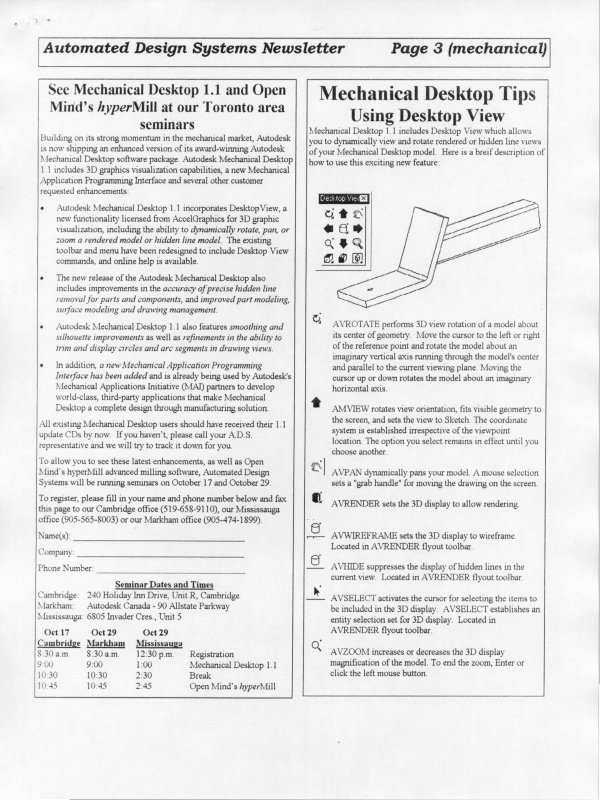
Mechanical Desktop Tips
Creating parametric and reference
ordinate dimensions
In Mechanical Desktop 1.2, you can now create “ordinate”
dimensions, both as parametric dimensions as you are
constraining your sketch, and as reference dimensions, once you
have placed your part into a “drawing” view for detailing.
To create parametric ordinate dimensions, perform the
following steps:
1. Create your sketch and profile it as you normally would.
2. Start dimensioning your sketch. Select an entity at your
“0,0” location with your first dimension pick in response to
the “Select first object:” prompt.
3. Select a placement point for the dimension. A normal
dimension is placed.
4. Type “O” for “Ord” in response to the prompt for the
dimension value. The dimension changes to your first
ordinate dimension in that axis with a value of 0.0000.
5. Press [ENTER] to confirm the placement of the first
ordinate dimension, or pick a new spot for the dimension.
The default position for any future dimensions during this
command will be dependent on the placement of this first
oridinate dimension.
6. Select the “next object for ordinate dimension” and adjust
the placement or dimension value, as appropriate. Continue
placing dimensions as required.
7. To dimension the other axis, finish the command and then
repeat steps 2 through 6.
If you need to add a parametric dimension later on, or if you
want to add a reference dimension while in “drawing” mode,
simply dimension between the first 0.0000 dimension and the
entity. As soon as you select the 0.000 dimension, you will be
prompted to “Select next object for ordinate dimension.”
Mechanical Desktop for R14 will be
available in the fall
With the impending release of AutoCAD Release 14, the inevitable
question that arises is, “When will Mechanical Desktop be available
with Release 14”?
The current version of Mechanical Desktop is 1.2, and it only runs
with AutoCAD Release 13c4a. The R14-compatible version of
Mechanical Desktop will be available in the fall. It is too soon to
have an accurate ship date, though.
RADAN releases powerful sheet metal
unfolding package for Mechanical Desktop
If you manufacture products that incorporate sheet metal parts, you
can reduce design cycle time and increase quality by incorporating
AutoSM from Radan Computational Ltd. of Somerset, UK.
AutoSM works directly with Mechanical Desktop geometry and
constraint data to provide you with maximum productivity and
quality in sheet metal design.
With AutoSM, you construct Mechanical Desktop models of sheet
metal components quickly and easily using automatic sheet metal
face and bend functions. Because AutoSM operates as an integral
part of Mechanical Desktop, it is simple to learn and easy to use, and
you can be sure of data compatibility with the entire design team.
AutoSM allows you to:
· create 3D sheet metal models from existing 2D AutoCAD data
· rapidly construct 3D sheet metal components by clicking on
component edges and adding faces
· create multiple sheet metal faces or features with a single
command
· punch holes with user-defined tool shapes
· automatically create sheet metal “shells” from solids
· Automatically insert bends between sheet metal planes
· Generate accurate flat-blank geometry as standard AutoCAD
2D data
At only $3,500, AutoSM is a fraction of the price of the competitive
UNIX-based products. For more information, please contact your
nearest Automated Design Systems office.